SO-101 Bone Rover
A generated, FEA-checked mobile base for the SO-101 arm with two encoder gearmotors, a swivel caster, a mast camera and a wrist camera, printable on a Bambu A1 mini in four pieces.
SO-101 Bone Rover · browser model
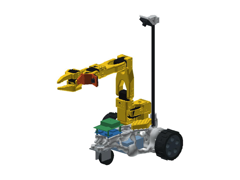
Reference pose. Move the arm on the rover in 3D, or read the model reference below.
Drag to rotate the view. Each slider changes one model joint. These are source-model angles, not calibrated hardware limits.
Visual exploration only. No physics, collision checks or connection to a robot. Frame strength figures come from the FEA described below.
Model reference and source
The source uses new-calibration virtual zero. These are source-model angles, not readings from the author’s arms. The gripper is angular in this URDF, not the LeRobot 0–100 opening mapping.
- Shoulder pan
- -110.0° to 110.0°
- Shoulder lift
- -100.0° to 100.0°
- Elbow
- -96.8° to 96.8°
- Wrist pitch
- -95.0° to 95.0°
- Wrist roll
- -157.2° to 162.8°
- Gripper angle
- -10.0° to 100.0°
Rover geometry from mayphus/so101-bone-rover; arm meshes simplified from TheRobotStudio’s pinned SO-101 source. Structured model · Conversion and attribution · Existing Apache 2.0 license.
Topology optimization · FEA · Bambu A1 mini · two motors
A mobile base for my SO-101 arm, grown rather than drawn. Every strut sits where a load runs from the arm, battery, motors or camera mast down to two driven wheels and one caster. The frame prints as four pieces on a 180 mm bed and bolts together through rounded knuckles where a strut crosses a cut.
Status on 12 November 2026
Designed, checked by FEA and packaged for printing. The first test piece (the front body, at low infill) is printing. Nothing has been driven yet; motor, wheel and caster dimensions still need checking against the parts as delivered.
What it is
| Part | Choice |
|---|---|
| Drive | 2 × JGB37-520 12 V gearmotor with Hall encoder (1:90), 100 mm treaded wheels at the back, about 0.58 m/s |
| Nose | One 2" rubber swivel caster: three contact points stay on uneven ground |
| Electronics | Waveshare General Driver for Robots (ESP32, both motors and encoders); optional Raspberry Pi 5 stacked on it; 3S pack under the arm |
| Cameras | A 32 × 32 mm USB camera on the official SO-101 wrist mount, plus a wide-angle one on a 380 mm mast behind the arm. No depth camera |
| Frame | ~441 g printed (estimate), four pieces, all within 180 mm |
How the frame was generated
- Design space and keep-outs. Motors and their encoder plugs, wheels, the caster's swing circle, the battery bay and cable paths are kept clear; the arm pad (the SO-101 base outline with four M5 inserts), motor face plates, caster bosses, driver bosses and mast socket are fixed solids.
- Optimization. 3D SIMP topology optimization on a 6 mm hex grid with 13 load cases: arm weight, reaching forward, backward and sideways, base twist, push and brake, battery, boards, motor torque and weight, a knock on the camera mast, and the caster plate pressing on every bolt. A 45° overhang rule keeps it printable without supports where possible.
- Smoothing and joints. The density field becomes a smooth surface; exact flat features are added back; joints grow out of the same field as rounded knuckles with M3 screws into heat-set inserts.
- FEA-guided clean-up. A first FEA pass finds dead fins (almost no stress) and thin load-carrying bridges; fins are removed and bridges thickened to at least 5 mm, then the frame is checked again.
FEA check (PETG, 2.5 mm voxels)
| Load case | Safety factor |
|---|---|
| Arm reaching forward, 200 g payload, 2× dynamic | 89× |
| Arm reaching sideways, 200 g payload, 2× dynamic | 99× |
| 3 g bump: arm, battery, motors, boards, mast | 106× |
| Both motors at stall torque | 137× |
| Camera mast knocked sideways, 3 g | 40× |
Frame flex moves the gripper at most 0.15 mm at full reach. Strength is not the limit; printability is. The knuckle joints are modelled as bonded, so the screws themselves are not checked, and real prints at low infill are softer than solid plastic.
Limits
- Reaching fully backward past the rear axle with a load can tip the base over its wheels; the work area is in front, where the mast camera looks.
- The 3D view above is visual only: the six SO-101 joints move, the rover does not drive, and nothing connects to hardware.
Source
Code, print-ready STLs, the print guide and the design history are in mayphus/so101-bone-rover. The arm model and wrist camera mount come from TheRobotStudio's SO-ARM100 repository under Apache 2.0.