Before opening anything, the cameras show useful signs: LED state changes, reset response, and whether the pan/tilt motor still moves.
hardware investigation
3 TP-Link Security Cameras
A curiosity teardown of three cheap broken cameras: power them on, see what still moves, open the roughest one, and map the hardware instead of treating repair as the main goal.
Summary
This page is about curiosity: how a consumer camera is built, what survives after years of use, and which parts become visible once the shell is open.
Two white cameras powered up and behaved like partial systems, which makes them more useful as comparison objects than as immediate teardown victims.
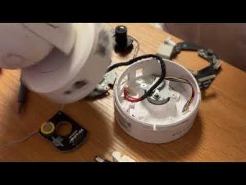
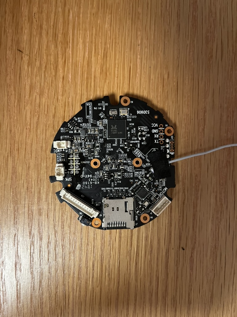
The opened unit exposed the PCB, camera module, stepper motor, speaker, microphone, SD-card slot, IR LED, light sensor, and power/network sections.
The follow-up tried USB-TTL because serial output can reveal boot behavior. Silence was still information about how far the board was getting.
Steps
- 01
Power on each camera, press reset, watch LEDs, and see whether the motor still moves.
- 02
Use app pairing and network discovery as quick clues about what part of the system may still be alive.
- 03
Open the roughest unit as a physical guide for snap locations, board layout, and how the camera is assembled.
- 04
Check UART pads as a curiosity path into the boot process, not as a promise that the camera needs to be repaired.
Hardware map
main PCB
camera module
stepper motor
speaker
microphone
SD-card slot
IR LED board
light sensor
UART pads
power conversion